Welcome to the
! Please enjoy our special offers for you

Galaxy S25+ Front Camera

Replacing the front camera on the Galaxy S25+ requires precision, proper tools, and careful handling of internal components. This step-by-step guide walks you through the complete disassembly and reassembly process, from safely removing the back cover and main board to preparing the new camera module with fresh adhesive. Whether you are restoring camera functionality or performing a professional repair, follow each instruction closely to ensure a safe and successful front camera replacement.
A blue Galaxy S25+ leaning against a stack of books, showing a selfie on its screen.

Galaxy S25+ Front Camera

Note
Remove the Back Cover first before you begin.

Galaxy S25+ Front Camera Disassembly

Galaxy S25+ Front Camera Disassembly
1

Check the 13 screws on the top of the rear and remove them using a cross-head screwdriver.
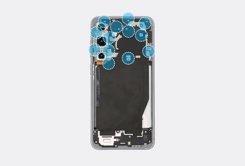
Internal view of Galaxy S25 Plus with blue highlights on thirteen screw locations around the top components.

Caution
Be careful not to damage the main board and near components.
Note
Check the number of screws that have been removed, and store them carefully to make sure that no unassembled screws are left inside the device during assembly.
2

Using the tweezers, separate the NFC antenna connector.
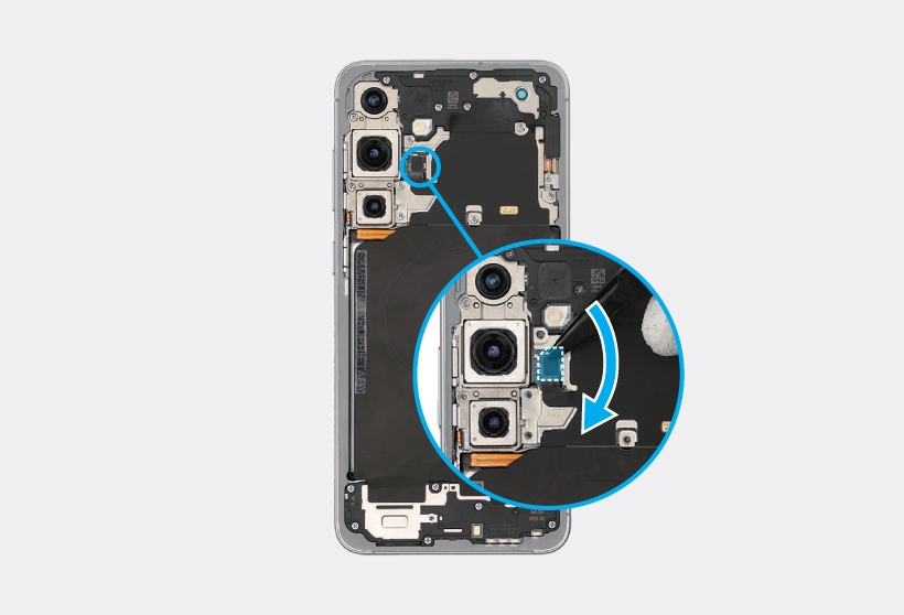
Magnified view showing tweezers disconnecting a small ribbon cable from the main circuit board.

Warning
  • Make sure to first disconnect the battery connector for your own safety.
  • Be careful not to damage the battery.
Caution
  • Be careful not to damage the main board and near components.
  • Be careful not to damage the NFC antenna connector and the FPCB cables.
  • Be careful not to tear any connected components near the wireless charging module.
  • Ensure that the wireless charging module is unfolded to prevent damaging the FPCB.
3

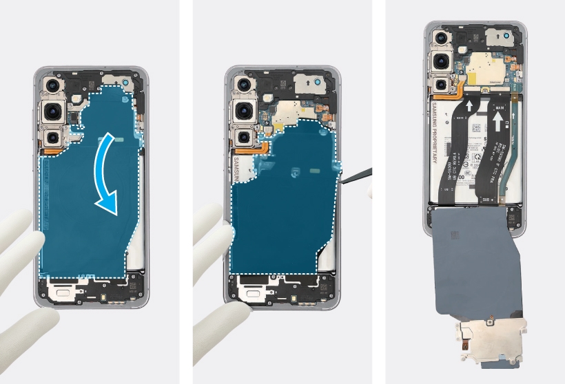
Using the tweezers or your fingers, lift up on the right of the metal plate carefully and pull it out from the device, and tilt it back to downward slowly.
Sequence showing the removal of the metal plate from the Galaxy S25 Plus.
4

Then, disconnect the battery connector from the main board using the tweezers.
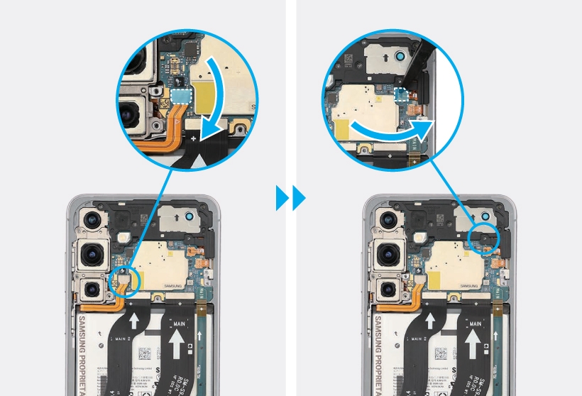
Two magnified views showing a battery connector being disconnected.

5

Using the tweezers, disconnect the top FRC connector and lift up on the separator groove of the rear top and remove it carefully.
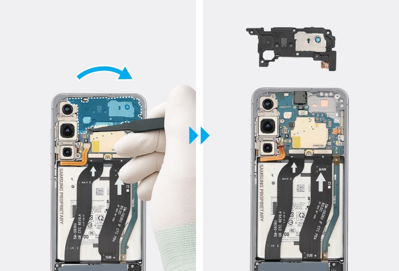
Tweezers lifting the top FRC connector away from the phone body.

6

Using the tweezers, disconnect the front camera connector and 3 flex cable connectors from the main board. For the United States 5G devices, disconnect the additional 5G mmWave antenna connector.
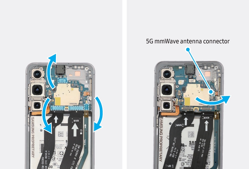
Sequence showing various connectors being flipped up, including the 5G mmWave antenna connector.

Warning
Be careful not to damage the battery.
Caution
  • Be careful not to damage the battery connector, main board, and near components.
  • The FPCB cables have to be positioned outside so as not to interfere when disassembling the main board.
Notes
  • The 5G mmWave antenna module and its connectors are only available in United States devices.
  • The cables and connectors may vary depending on the country, region, or specification.
7

Using the tweezers, lift up on the separator groove of the main board, and remove it carefully.
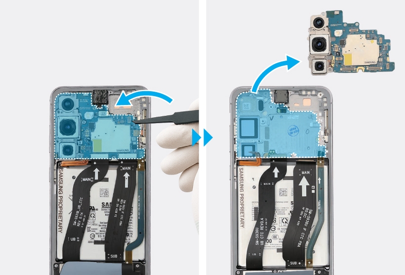
Tweezers removing the rear camera module from the top-left section of the internal frame.

Caution
The FPCB cables have to be positioned outside so as not to interfere when disassembling the main board.
8

Heat the microwaveable heating bag and apply it to both the front and back sides of the front camera module for 3 minutes.
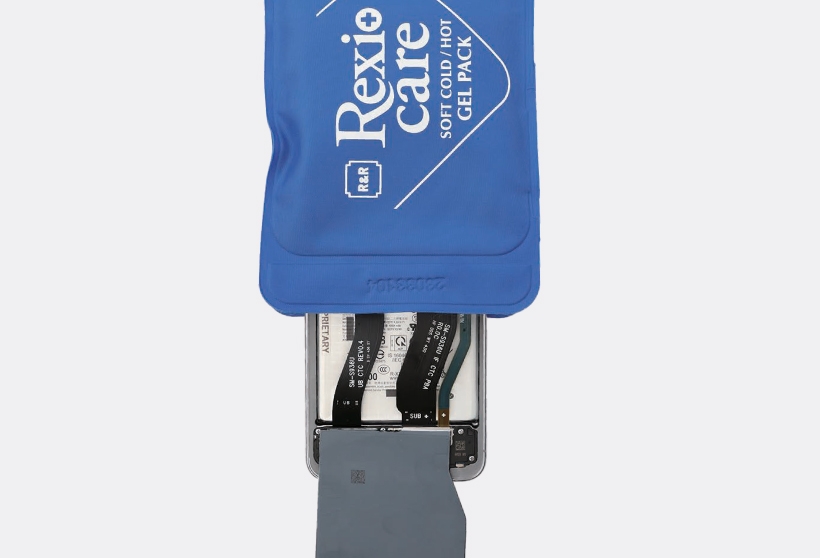
Rexio care gel pack being applied over the lower internal components and battery area.

Warning
  • It is possible for the device or battery to be damaged by heat.
  • Do not heat the device in a microwave. Doing so could cause an explosion.
  • If your device’s glass breaks, the debris can cause injury to your hands or other body parts. For your safety, attach an acrylic protective cover before disassembling the device.
Caution
  • Follow the heating bag’s instructions for heating. The recommended time for heating the bag is 50 seconds in a 1000 W microwave and 70 seconds in a 700 W microwave. (Correct temperature for use: 55-65 ℃.)
  • Be careful not to damage the device through excessive heat. (It is recommended to disassemble the device in an area with a temperature gauge.)
9

Before the heat cools with the heating bag applied, remove the adhesive between the front camera and the screen module using the SIM card tray ejection pin.
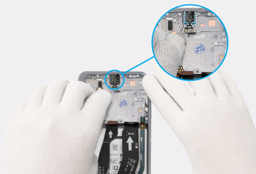
Close-up of gloved hands using a SIM card tray to lift the adhesive between the front camera and the screen module.

Caution
As the adhesive securing the camera is very strong, work slowly.
Note
If you have trouble removing the adhesive, heat the microwaveable heating bag additionally, and apply it to the front camera module to further soften the adhesive. When reheating, it should be heated no longer than 30 seconds.
10

Then, remove the front camera carefully using your fingers, and leave the camera lens facing up.
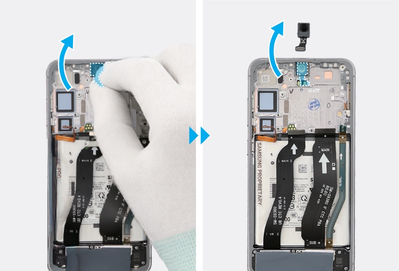
Sequence showing the front camera module being lifted and completely removed from the frame.

Read less

Galaxy S25+ Front Camera Reassembly

Galaxy S25+ Front Camera Reassembly
Warning
Leaving screws inside the device may damage internal components, such as the battery. When assembling, be extra careful not to leave any unassembled screws inside the device.
1

Using the tweezers, remove the adhesive and tape from the front camera hole completely.
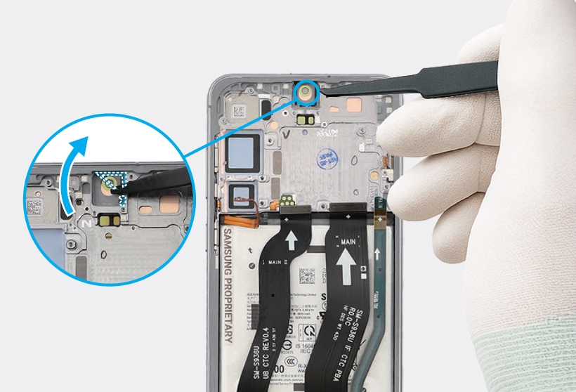
Close-up of the Galaxy S25 Plus internal view showing tweezers removing the adhesive and tape from the camera hole.

2

Remove the release film of the new front camera side adhesive tape. Align the tape with the left side of front camera hole vertically and attach it accurately. Then, gently press down the tape with the tweezers so that the tape can be attached well.
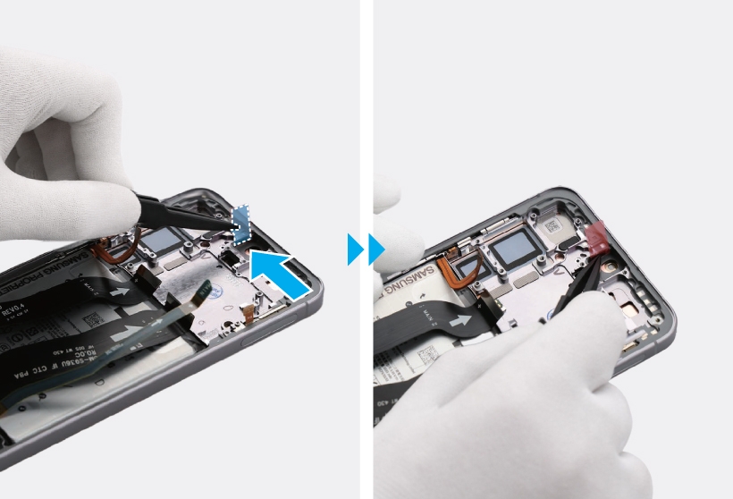
Two-step sequence of the Galaxy S25 Plus internal view showing tweezers removing the release film and attaching the side adhesive tape.

3

Remove the release film of another new front camera side adhesive tape. Align the tape with the right side of front camera hole vertically and attach it accurately. Then, gently press down the tape with the tweezers so that the tape can be attached well.
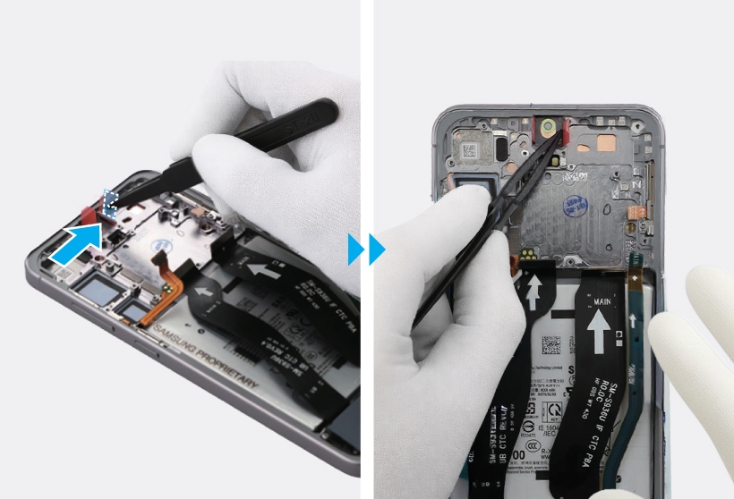
Two-step sequence of the Galaxy S25 Plus internal view showing tweezers attaching the red adhesive tape to the right side of the camera hole.

4

Using the tweezers, remove the protruding release films of the 2 tapes attached to the left and right sides of the camera hole.
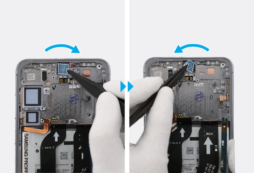
Two-step sequence showing tweezers removing the blue release films from the camera adhesive tapes.

5

Remove the clear film from the new front camera main adhesive tape with the tweezers.
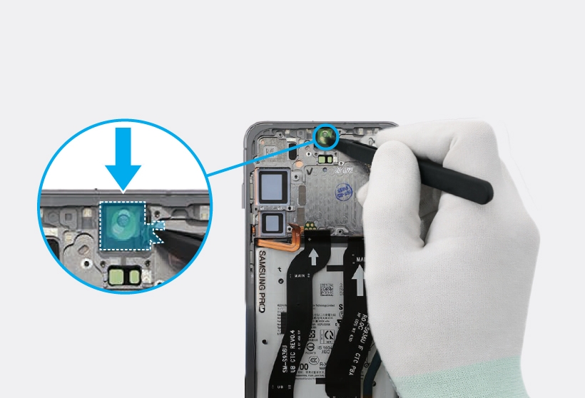
Close-up of the Galaxy S25 Plus internal view showing tweezers removing the clear film from the adhesive tape.

6

Align the outside shape of the adhesive tape with the position of the camera hole and attach it accurately. Then, gently press down the tape with the tweezers so that the tape can be attached well.

Two-step sequence of the Galaxy S25 Plus internal view showing tweezers aligning and pressing the adhesive tape onto the front camera. 

7

Using the tweezers, hold the protruding clear film of the attached tape and remove it carefully.
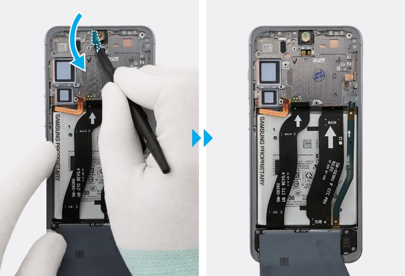
Two-step sequence of the Galaxy S25 Plus internal view showing tweezers removing the clear film.

8

Remove the release film of a new front camera top adhesive tape with the tweezers. Align the adhesive tape to the top of front camera and attach it accurately. Then, gently press down the tape with tweezers so that the tape can be attached well.
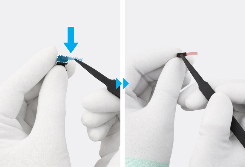
Two-step view showing gloved hands using tweezers to remove the release film and press the adhesive tape onto the detached front camera.

Caution
Be careful not to damage the camera.
9

Using the tweezer, remove the release film of the front camera top adhesive tape.
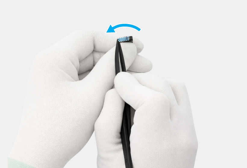
Gloved hands using tweezers to remove the release film from the top adhesive tape on the detached front camera.

10

Using the tweezers or your fingers, place the front camera in the camera hole so that the lens faces forward, and gently insert the front camera.
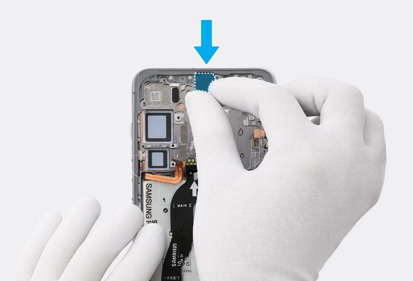
Gloved hands inserting the front camera module into the camera hole within the Galaxy S25 Plus internal frame.

Caution
  • Be sure to place the camera in the correct position.
  • Be careful not to damage the camera lens.
  • Be careful not to damage and scratch the camera module.
11

Press down softly and evenly on the camera module so that the front camera can be fully inserted.

Gloved hand pressing down on the front camera module within the Galaxy S25 Plus internal frame to secure it. 

12

Align the main board module onto the device frame. After attaching the upper part of the main board diagonally on the screen module, assemble the lower part.

Two-step sequence of the Galaxy S25 Plus internal frame showing the main board being aligned and then seated into the device chassis. 

Warning
Be careful not to damage the battery.
Caution
  • Be careful not to damage the battery connector.
  • The FPCB cables have to be positioned outside so as not to interfere when assembling the main board.
13

Using the tweezers or your fingers, connect the front camera connector and the 3 flex cable connectors on the main board. For the United States 5G devices, connect the 5G mmWave antenna connector on the main board.
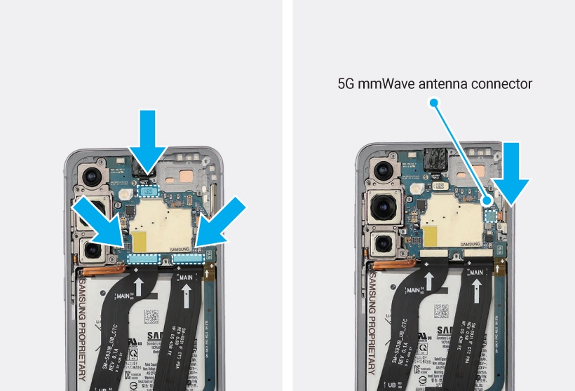
Two-step sequence of the Galaxy S25 Plus internal view showing the connection of the front camera, three flex cables, and the 5G mmWave antenna to the main board.

Warning
Be careful not to damage the battery.
Caution
Be careful not to damage the main board.
Note
  • The 5G mmWave antenna module and its connectors are only available in United States devices.
  • The cables and connectors may vary depending on the country, region, or specification.
14

Using the tweezers or your fingers, place the rear top in the correct location and gently press down to secure it in its position until you hear a locking sound. Then, connect the top FRC connector to the main board.
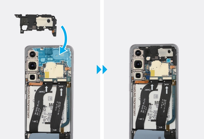
Two-step sequence of the Galaxy S25 Plus internal view showing the rear top component being placed onto the upper frame and the top FRC connector being attached to the main board.

Caution
Be careful not to damage the main board and near components.
15

Connect the battery connector to the main board.
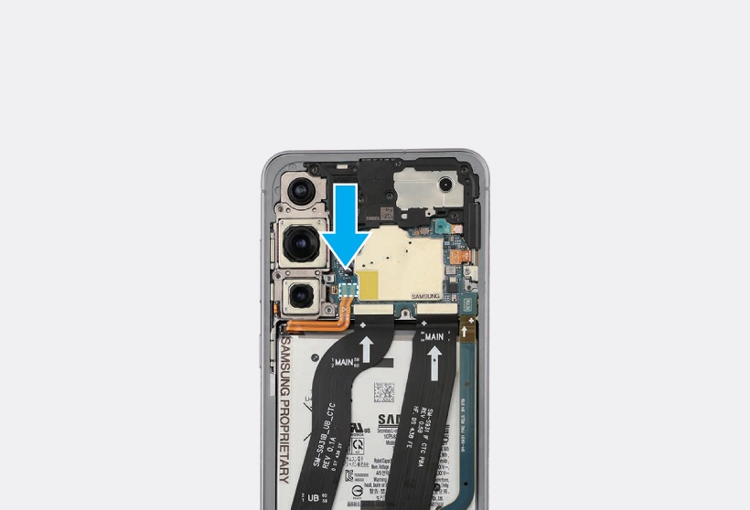
Galaxy S25 Plus internal view showing a blue arrow pointing to the battery connector as it is being attached to the main board.

Warning
Be careful not to damage the battery.
Caution
Be careful not to damage the battery connector and near components.
16

Hold the tilted wireless charging module with the tweezers or your fingers and carefully assemble to its original state.
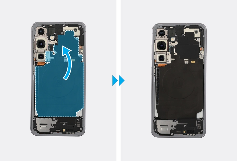
Two-step sequence of the Galaxy S25 Plus internal view showing a blue arrow and highlighted area indicating the placement of the wireless charging module.

Warning
Be careful not to damage the battery.
Caution
  • Be careful not to damage the NFC antenna connector and the FPCB cables.
  • Be careful not to tear any connected components near the wireless charging module.
  • Ensure that the wireless charging module is unfolded to prevent damaging the FPCB.
17

Connect the NFC antenna connector to the main board.
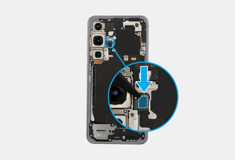
Galaxy S25 Plus internal view with a close-up inset showing tweezers and a blue arrow guiding the NFC antenna connector onto the main board.

Caution
Be careful not to damage the main board and near components.
18

Check the screw 3428 (13ea) at the 13 different points on the top of the rear and fasten them using a cross-head screwdriver.
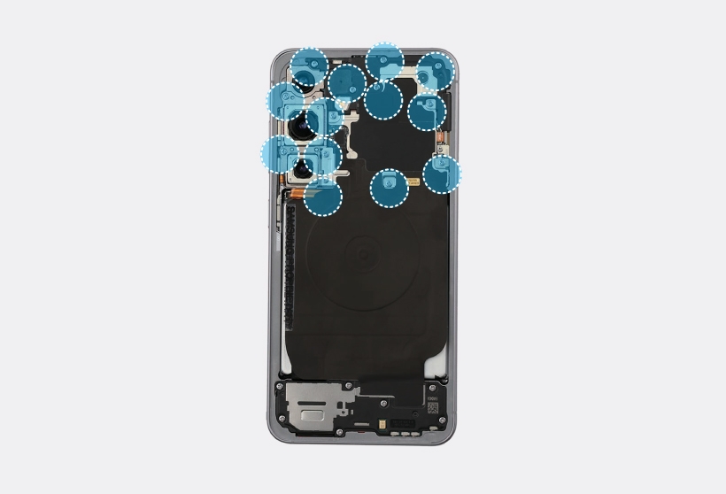
Galaxy S25 Plus internal view with 13 dotted blue circles highlighting the specific locations for screw reinsertion across the upper components.

Caution
Be careful not to damage the main board and near components.
19

Check carefully with your fingers to see if there are any screws or other foreign substances inside the device (battery, PBA, cable, etc.). Shake the device lightly with the back of the device facing down to remove any remaining screws.


Side view of a silver S25 Plus with three blue arrows pointing down below the device. 

Note
Reassemble the Back Cover to complete assembly.
Read less
Was this content helpful?
Table of contents
We're here for you

Contact Samsung Support

Contact us online through chat and get support from an expert on your computer, mobile device, or tablet. Support is also available on your mobile device through the Samsung Members App.
Fast, easy checkout with Shop Samsung App
Easy sign-in, Samsung Pay, notifications, and more!
Or continue shopping on Samsung.com
×
The Shop Samsung app
Free standard shipping, exclusive offers and financing options.
GET
×
The Shop Samsung app
Free standard shipping, exclusive offers and financing options.
GET
×

You Are About To Be Redirected To Investor Relations Information for U.S.

Thank you for visiting Samsung U.S. Investor Relations. You will be redirected via a new browser window to the Samsung Global website for U.S. investor relations information.
CANCEL
CONTINUE
×

Redirect Notification

As of Nov. 1, 2017, the Samsung Electronics Co., Ltd. printer business and its related affiliates were transferred to HP Inc.

For more information, please visit HP's website: http://www.hp.com/go/samsung


Select CONTINUE to visit HP's website.

CANCEL
CONTINUE